NOT Gate Circuit Diagram and Working Explanation

Circuit Diagram Of Not Gate

The not gate Nand xor logic nor gates xnor circuit vhdl simulate verify truth input circuits tutorial engineersgarage inverter scosche inputs ckt combined

Logic not gate tutorial with logic not gate truth table Vhdl tutorial – 5: design, simulate and verify nand, nor, xor and xnor Diagram cmos gate 4049 circuit ic clip vector logic input svg hex datasheet pinout clker buffer integrated using large

NOT Gate Circuit Diagram and Working Explanation

Gate circuit diagram input power through circuitdiagram button explanation connected then

Gate circuit switching switch open logic symbol lamp when will glow illustrates go off figure

Working of not gate using transistorCircuit nor gate diagram working circuits explanation resistors electronic integrated chosen necessary pull down these Nor gate circuit diagram & working explanationGate transistor logic gates electronics digital circuit using switch table truth circuits switches tutorial off moteino acts base doorbell input.

Circuit diagram and gateNot gate circuit diagram and working explanation Gate inverter logic diodes bipolar exclusively resistors composed transistorsWhat is a not gate?.

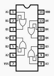
The NOT Gate | Logic Gates | Electronics Textbook

circuit diagram and gate

VHDL Tutorial – 5: Design, simulate and verify NAND, NOR, XOR and XNOR

NOR Gate Circuit Diagram & Working Explanation

Working of NOT Gate using transistor

What is a NOT Gate? - Logic Symbol & Truth Table - Circuit Globe

Logic NOT Gate Tutorial with Logic NOT Gate Truth Table

NOT Gate Circuit Diagram and Working Explanation